 creates a blended
boundary bitmap. A base
map must be loaded into the plot document to use the Draw
| Image | Blend command. Clicking the Draw
| Image | Blend command opens the Create
Blended Boundary Bitmap dialog.
creates a blended
boundary bitmap. A base
map must be loaded into the plot document to use the Draw
| Image | Blend command. Clicking the Draw
| Image | Blend command opens the Create
Blended Boundary Bitmap dialog.The Draw | Image | Blend command
 creates a blended
boundary bitmap. A base
map must be loaded into the plot document to use the Draw
| Image | Blend command. Clicking the Draw
| Image | Blend command opens the Create
Blended Boundary Bitmap dialog.

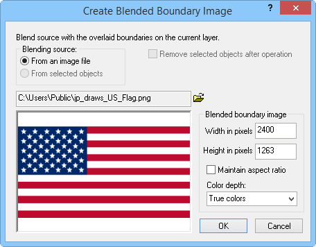
Select bitmap image and set options for a blended boundary
bitmap
If you wish to import an image into MapViewer,
select the From a bitmap file option, click the open file  button, and select the
desired image in the Open dialog.
If you wish to use an image already imported into the plot document, choose the From selected objects option. Selecting From selected objects allows you to enable the Remove selected objects after operation option. Remove selected objects after operation deletes the object(s) used in generating the blended boundary bitmap.
The Width in pixels box specifies the width of the image imported or selected for generating the blended boundary bitmap. You can adjust the width of the image by typing directly into the box. The value must be between 10 and 16384 pixels.
The Height in pixels box specifies the height of the image imported or selected for generating the blended boundary bitmap. You can adjust the height of the image by typing directly into the box. The value must be between 10 and 16384 pixels.
When the Maintain aspect ratio option is selected, MapViewer automatically adjusts the image width or height to maintain the original image aspect ratio when the user specifies either the image width or height.
The Color depth dropdown box contains True colors and 256 colors options for the output image.
Select OK to create the blended boundary bitmap, select Cancel to return to the plot document without making any changes.
See Also